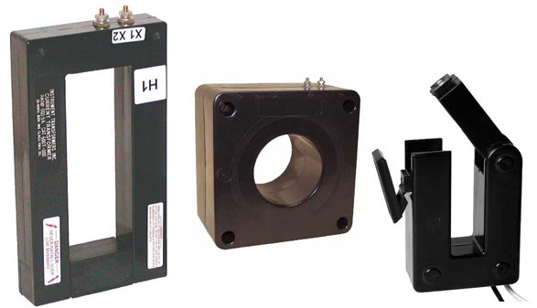
 The Current Transformer (CT) is used to sense AC current in single-phase or three-phase mains circuits. The CT typically has a 1A or 5A AC secondary that connects to a current, power or energy meter. This allows the meter to be located away from the main wiring. CTs are available in various sizes and styles, with standard ratios of 50:5 to 4000:5. Split core models easily retrofit around existing wiring. Solid core models offer lower cost.
Some monitoring systems are supplied with current transformers that have a voltage output. The full scale on these devices is not standardized but usually is between 0.3-2V AC. Despite the lack of standardization, there are several advantages to using a CT with a voltage output. It eliminates the need for heavy leads or a high VA rating. The voltage output also allows a greater distance between the CT and the meter. Another consideration – an open secondary loop on a 1A or 5A CT can produce hazardous high voltage. Models with a voltage output are clamped to a safe level.
Current transformers are specified by size (VA rating), ratio and accuracy. The VA rating determines the maximum secondary impedance (lead+terminal+meter impedance) that can be driven at the stated accuracy. Metering CTs are specified for a 0.9 power factor at 60 Hz. Relaying CTs are specified at 0.5 PF.
Current Transducers also use a solid-core or split-core transformer to sense an AC current. However, they have circuitry to convert the output to a low level DC signal, either volts or mA. Models with a DC voltage or 1mA current output may be self-powered. Models with a 4-20mA DC output usually require an external power supply.
See product info for Current Transformers or AC Current Transducers.
Current Transformer Application Note and Wire Length Chart (pdf)
Current Transformer Ratings for Various Motor Sizes (pdf)
