Industrial sensors for pressure, flow, temperature, position and other process parameters typically include signal conditioning that generates a dc output. This output can be either a voltage or a current. Which output is best for a particular application depends on several factors.
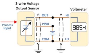
 Most sensors with a voltage output have three connections – signal out, power in and a common terminal which serves as both signal low and power low. To read the sensor output, a dc voltmeter is connected between signal out and common. Typical output voltage ranges for process signals are 0 to 1V, 0 to 5V, 1 to 5V, and 0 to 10V. A benefit of the offset zero on the 1-5V range is that a broken wire or failed sensor is easily detected.
Many sensors include a shield on the output leads, which should be connected to earth ground. Shielded cable is often used on both the sensor and meter wiring to reduce electrical interference. This can be particularly important for long runs or electrically noisy installations. The voltmeter may have adjustable filtering so the user can obtain stable readings on the digital display. Filtering reduces the effect of both external interference and a jittery sensor signal. Some precision sensors include a fourth wire to separate signal low from power supply low. This eliminates any error due to current flow (IR drop) in the common lead.
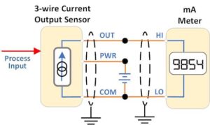
 A popular current output configuration also uses 3 wires for output, power and common. A dc milliammeter is connected between output and common. Typical output ranges are 0 to 1mA, 0 to 20mA, and 4 to 20mA. A voltmeter can be used in place of the mA meter by adding a resistor between HI and LO. This converts the current signal to a voltage signal. Frequently used values are 1kΩ to convert 1mA to 1V, and 500Ω to convert 20mA to 10V. With the 4 to 20mA output, a zero sensor input generates a 4mA output. A broken wire, failed sensor or loss of power is easily distinguished from a valid zero signal level. Shielded leads are recommended for sensors with a current output, as well as the milliammeter input connections. If shielding is not available, twisted-pair wiring will reduce normal mode interference.
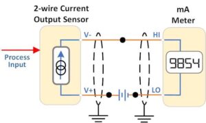
 The simplest current output scheme combines power and signal on two wires. The sensor and meter are connected in series with a dc power supply. The power supply voltage must be higher than the voltage drop across the sensor and meter at maximum signal level (including overrange). With a 4 to 20mA output, some current always flows in the loop. Sensor operating power is obtained from this loop current. The two-wire method requires an offset zero value. It does not work for 0-1 or 0-20 mA sensor outputs. Three system connection points (• in the diagrams) are still required. See the March and April 2021 blogs for more information on implementing 4-20mA loops.
Here are some of the factors to consider when selecting either voltage or current output:
Sensor Capability
Current output is the most common format for industrial sensors. The sensor specifications will indicate whether the output is voltage or current. Popular models can sometimes be ordered with either type of output. A few versatile sensors are field configurable to select voltage or current and change the output range.
Meter Type
Ideally the meter input function and range will match the sensor output. A voltmeter can easily measure mA current levels with the addition of a shunt resistor. However, the reverse is not true – a milliammeter cannot be easily adapted for voltage measurements. Fortunately, many process meters have a ‘universal’ input that can be configured for either a voltage or current input and popular signal ranges.
Available Power
20mA and 10V outputs usually require a dc supply from 15 to 30V. Sensors with 1mA or 5V outputs can operate from a lower supply voltage. An issue in a control panel is the availability of external power to operate the meter. If no power is available, then a variety of loop-powered meters are manufactured for use with 4-20mA sensors.
Distance
The primary issue with distance is signal degradation due to noise pickup. For voltage outputs, a higher full-scale value provides a better signal-to-noise ratio. Current loops are generally less susceptible to noise than voltage circuits.
Wiring
The sensor output leads should be run together to minimize noise susceptibility. The same applies to the HI and LO meter leads. Twisted pair with shield provides additional noise protection. For voltage outputs, COM wiring should be routed carefully to avoid introducing measurement errors due to currents from other devices. For 20mA outputs, the voltage drop in long leads may require heavier gauge wire or a higher supply voltage.
Fault Detection
The voltmeter used with a voltage output sensor typically has a high input impedance (1MΩ or more). A broken input lead may pick up enough noise to be mistaken for a valid signal. The lower impedance of the milliammeter (or voltmeter with a shunt resistor) is much less susceptible to this error. The use of an offset zero scale, either volts or milliamps will make this fault easy to detect.
Testing
Multimeters and process calibrators are common test tools for use on circuits with either type of sensor output. Voltage outputs are easier to check since the tester is placed in parallel with the meter. For current outputs, the tester must be inserted in series with the meter. This requires opening one of the signal connections.
To summarize, the advantages of a current output are:
– Broader selection of industrial sensors
– Lower noise pickup
– Longer useable distance from sensor to meter
– Better fault detection
– Can be used with a milliammeter or voltmeter
The advantages of a voltage output are:
– Lower power consumption
– Simpler testing
Weschler offers an extensive selection of sensors to measure electrical and physical parameters. With careful attention to sensor setup, meter configuration and installation details, either output type can operate successfully in industrial applications.
