For two AC power systems to be interconnected (paralleled), they must be synchronized. This means they must be operating at the same voltage, the same frequency, and the same phase angle. Only when all three parameters match is it safe to connect the two systems. Paralleling two unsynchronized AC systems will cause a sudden current surge and mechanical stress on rotating equipment. This can disturb or severely damage one or both systems.
A synchroscope displays the frequency difference and phase angle between two AC power sources. It is used to match an auxiliary generator to the main power system, to synchronize a factory’s power plant with the utility’s power grid or when connecting one generating unit to another generating unit in a facility.
In addition to matching frequency and phase angle, systems to be interconnected must be operating at the same voltage. Separate indicators are often used to monitor this parameter. Polyphase systems also must have the same phase sequence. Since most synchroscopes are connected only to a single phase of the two systems, indicator lights or other instrumentation is needed to verify the sequence.
Analog Synchroscopes
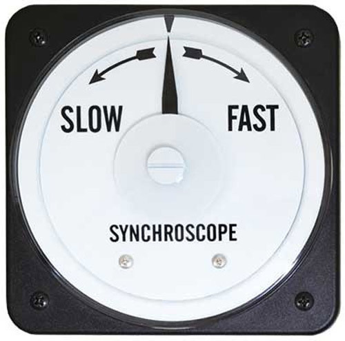 Analog synchroscopes are electrodynamic meters that rely on the interaction of magnetic fields to rotate a pointer, which is free to move continually through 360 degrees. A pointer moving clockwise indicates the generator frequency is higher than the reference (bus) frequency. A pointer moving anti-clockwise indicates the generator frequency is lower than the reference frequency. The speed of rotation is proportional to the frequency mismatch. An off-center static pointer indicates a frequency match, but a phase difference between the two systems. When the pointer is stable on the center arrow, the frequency and phase are matched. Analog synchroscopes operate over a limited frequency range – a few percent above and below the system’s nominal frequency. A damping vane inside the meter is used to smooth out vibration. For high-voltage systems, synchroscopes are connected through voltage transformers to reduce the meter’s input voltage to 120 volts.
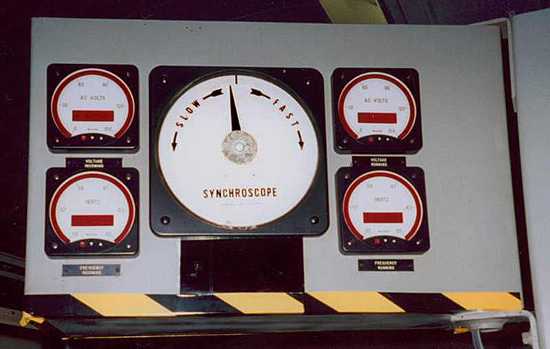 This control panel in a TVA power plant has a Weschler KI-261 8¾” Switchboard Synchroscope flanked by four BG241 Digital Bargraph Meters. The Bargraph meters monitor the voltage and frequency of each system. The KI-261 operates with 120V inputs at either 50 or 60Hz. A smaller switchboard synchroscope, the 4½” KI-241, is also available for 50 or 60Hz systems. High shock models in this size operate at either 60 or 400Hz.
Digital Synchroscopes
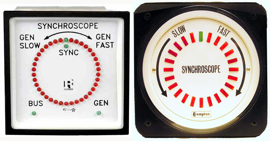 A basic digital synchroscope replaces the analog meter movement and pointer with a ring of discrete LEDs. The LEDs are activated to mimic the pointer movement of an analog synchroscope. A different color LED is used to indicate the “in phase” condition. The Sifam SQ Digital Synchroscope (left) has a DIN case with either a 96mm or 144mm square bezel. The rotation of the vector spot is with reference to the bus voltage. If the vector spot LED turns clockwise, the speed of the generator must be reduced. If the spot LED turns anticlockwise, the speed of the generator must be increased. The rate of rotation indicates the amount of frequency mismatch. A rotation time of 10 seconds infers a frequency mismatch of 0.1Hz at 50Hz. If the frequency matches & phase does not, then one red LED corresponding to the phase difference will glow. If the frequency & phase of the bus signal match the generator signal, the two green LEDs at the top center will illuminate.
The Crompton 077 Series Digital Synchroscope (right) operates in a similar manner. This model has a 4½” metal switchboard case. One unit handles both 50Hz and 60Hz. The input voltage (120, 240 or 480V) is specified when ordering. A synchro-check relay can be added to provide a contact closure for use by external control circuits.
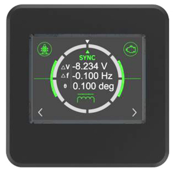 More sophisticated digital products display the frequency difference and phase difference directly. Some utilize a graphic display to emulate the circle of LEDs. The Byram Digital Synchroscope has a color touch screen that shows a visual representation of synchronization status, plus a digital readout of the voltage difference, frequency difference and phase difference. This reduces the need for the additional meters that are used with other synchroscopes. One model accepts direct connection of 100-500V inputs at 44-66Hz. The meter can be powered from either input or an auxiliary supply (typically 120VAC). A relay contact output is standard on this unit.
Related Products
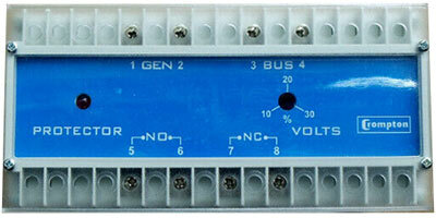 The synchro-check protective relay can be used to assist in paralleling two AC power systems. Contacts in the relay change state when the voltage level, phase relationship and frequency are within the selected synchronizing limits. As part of a manual control system, the operator adjusts the generator voltage (excitation) and generator speed (frequency) using a synchroscope and then attempts to manually close the breaker to connect the two systems. The synchro-check protector will ensure that the two systems are closely matched before permitting the breaker to close. As part of an automatic synchronizing arrangement, this relay can be used as an independent backup to ensure the two systems are suitably matched before the breaker can close. The Crompton 256-PLL Protective Relay shown here continuously monitors the voltage, phase and frequency of two supplies. A single set point adjustment permits the selection of suitable matching and a red LED illuminates when the relay is energized, indicating that it is safe to close the breaker.
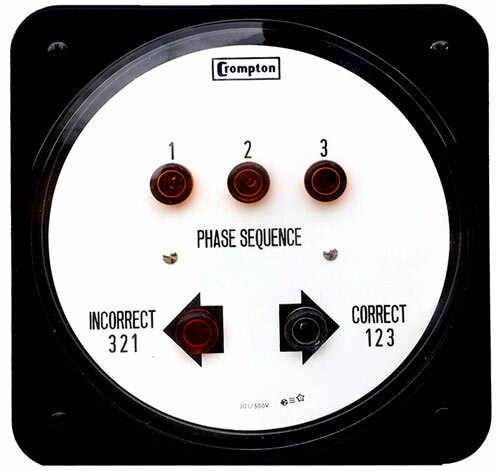 Another related product often used when paralleling three-phase systems is the phase sequence indicator. The phase sequence between two systems must be matched before they can be safely connected. Shown here is the Crompton Phase Indicator in a switchboard case. Two arrows show whether the phase sequence is correct or incorrect. The indicator also has a light for each phase, so loss of one phase is immediately visible.
Synchroscopes and related products are essential to the proper operation of both large and small power grids with multiple AC sources. A range of analog and digital models from various manufacturers are available to assist in paralleling AC systems.
