The table function is used to define the relationship between the input signal and the output reading in a digital panel meter (DPM). This allows the user to implement a complex output function or correct system errors. Here are some examples where a table increases the versatility or improves the performance of a DPM.
Scale an Input
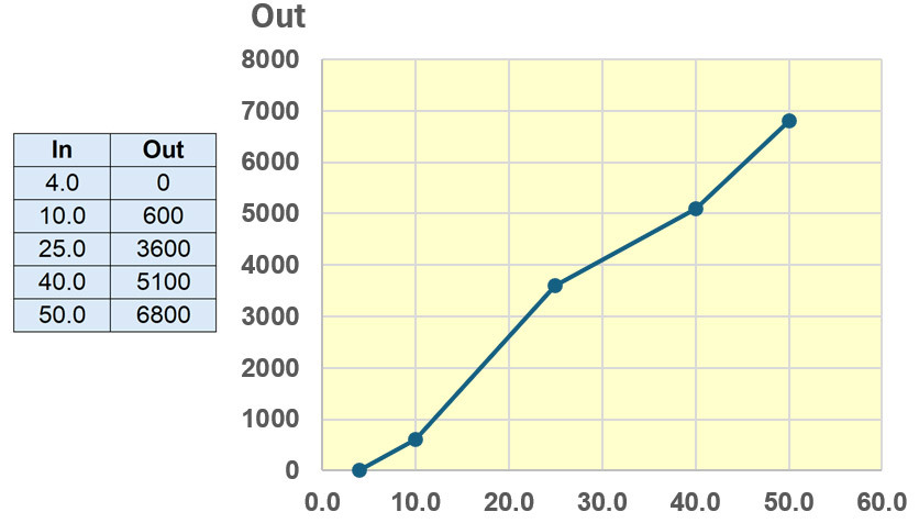 When a transducer is connected to a DPM input, it is usually desirable to have the meter display the transducer’s input rather than the meter’s input. A common application involves a 5A current transformer connected to a digital ammeter. Rather than display 0-5A, a table can be used to display the CT primary current. Another example: a smart sensor has a -50degC to +150degC range. The sensor’s 4-20mA output is connected to a digital milliammeter. A DPM table converts the mA input value into the corresponding temperature reading (e.g. 12mA=0degC).
 Units conversion is often done without a table, by using offset and gain adjustments. However, additional information can be included in the table. For example, it can indicate the over-range point on a transducer, even when that level is within the normal operating span of the meter. If the sensor has one gain for positive signals and a different gain for negative signals, a table easily handles this situation. While we generally discuss the table function as converting input level to displayed value, the actual table loaded into the meter converts A/D counts to display counts. The typical DPM does a linear extrapolation for a level between table values. More points in a table will more precisely define the output. Sophisticated DPMs, like the Laurel Laureate, use a computer app to simplify table creation and downloading to the meter.
Convert a Sensor Output
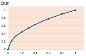 Some sensors have a non-linear electrical output that is defined by a table or a mathematical expression. For thermocouples, a table defines the sensor’s millivolts to degrees C relationship. For RTDs and thermistors, a table defines the ohms to degrees C conversion. Some flow sensors have a square law output. While advanced meters may have temperature or square root functions, they can also be implemented using a DPM table. The number of points is determined by the complexity of the input-output relationship and the desired conversion accuracy. In this simple example, more points are used for a 0 to 0.2 input, where the shape is rapidly changing. Fewer points are needed from 0.6 to 1.0, where it is slowly changing.
Display Tank Level
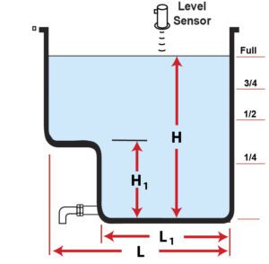 The table function is often used to convert a level measurement into a volume measurement. This is important where an irregularly shaped tank stores a liquid. For example, a rectangular (cuboid) tank has the profile shown. Liquid level H, as reported by the level sensor, indicates a full tank. Due to the step change at H1=0.45H:
At 0.31H, the tank is ¼ full.
At 0.61H, the tank is ½ full.
At 0.78H, the tank is ¾ full.
At ½H, the tank is only 42% full.
A 3-point table is used to model this profile. It can be set up to read either the percent full or the number of gallons remaining. This is a simplified example. The typical fuel or ballast tank in a ship has a much more complex shape in three dimensions. It requires more points to convert level to volume.
Improve Meter Accuracy
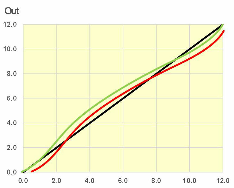 The table function can be used to improve the accuracy of a digital meter. The table provides more flexibility than the two-point calibration that meters normally use. Zero and full-scale adjustments correct offset and gain errors but cannot correct linearity errors. The meter response shown in red exhibits a zero offset, full-scale error and linearity errors. The ideal response is shown in black. Two-point calibration (green) improves the accuracy at both ends of the scale but increases the mid-scale error (for inputs from 2.0 to 8.0). All three errors can be corrected using a table. AC volts and amps functions typically have more offset and linearity errors than DC functions. They can benefit from using a table for calibration. The same technique can improve a sensor’s linearity and overall accuracy.
Other Examples
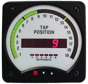 In a Load Tap Changer, a potentiometer is used to sense the position of a rotating tap switch. The table function in a Weschler BarGraph Meter converts the pot’s output voltage into a step number, which is displayed on both the bar and digital readout. The number of steps varies by application. This photo shows tap numbers from 1 to 19, which requires a 42-point table. The table could also be implemented as -9 to +9, with a center zero.
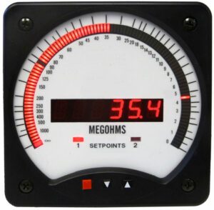 In the second example, an insulation measurement system has a 0 to 200μA dc output to indicate resistance from >1000MΩ to <1MΩ, with a midpoint around 35MΩ. A 40-point table in the bar graph meter converts the microamp input level into the correct resistance reading. This is shown on both the digital display and the bar display. The bar grows as the resistance decreases. A setpoint at 50MΩ warns of decreased insulation quality. A second setpoint at 5MΩ alerts to an immediate need for service. These points are user-adjustable to meet the requirements of each installation.
The table function is a feature that increases the versatility of a digital meter. It is one way to deal with typical issues of offset, gain, linearity and curve fitting. Tables can also be creatively used to address the requirements of unusual applications.
