The RS-485 standard (also known as ANSI/TIA/EIA-485) was developed in the 1980s to allow a master device to communicate with multiple slave devices. RS-485 defines a method for serial transmission using differential signal lines shared by up to 32 devices. Its advantages over RS-232 include higher noise immunity, higher speed, and longer distance. Communication is asynchronous (no system clock). A master device controls data flow to and from the slave device(s).
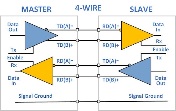
 RS-485 includes the full-duplex operation previously defined in RS-422. This scheme uses 4 wires for separate transmit and receive channels between the master and slave devices. Simultaneous transmission and reception of data by each device is possible in the configuration. The transmitter is a differential driver with a minimum output level of ±1.5V. Minimum signal level at the receiver input is ±200mV. The initial standard set a maximum speed of 10Mbps for distances less than 50ft (15m). The maximum distance of 4000ft (1200m) was limited to 100kbps. Improved drivers now allow speeds >30Mbps over short distances.
RS-485 operation requires that each transmitter output go into a tri-state (high impedance) condition when not sending data. This allows multiple transmitter outputs to be connected to the same wire pair. However, only one of these can be active at any time. Multiple receivers can also be connected, since each has an input resistance >12kΩ and a transmitter can drive a 54Ω load.
The master-slave scheme has one device that issues commands to the slave devices and processes their responses. Each slave device has a unique bus ID so it can be addressed individually by the master. Slave devices typically send data only in response to a request from the master. They do not communicate with each other. Systems with multiple masters are possible, but not common, since they add complexity to management of the data flow.
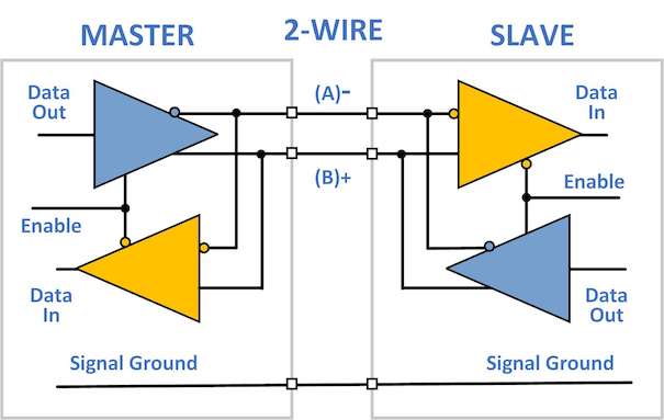
 The most popular configuration for RS-485 is half-duplex or 2-wire. This scheme uses one pair of wires to both send and receive data. All devices start in receive (listen) mode. The master switches to transmit mode and sends out a request. It then switches to receive mode. All slaves hear the request, but only the addressed device(s) act on it. If data is requested from a particular slave, it responds by switching to transmit mode and sending the data. It then returns to receive mode. The master receives the data and the cycle is complete. In some networks, the receiving device can add a turn-around delay to allow sufficient time for the transmitting device to switch from transmit to receive. A delay may be necessary at fast data rates or when using a bus converter (see below).
Connections
 RS-485 uses a multi-drop method to connect master and slave devices. This can be implemented as a trunk line between the furthest devices, with short taps to connect intermediate devices. However, a trunk can be cumbersome to wire. Another method is to use an open daisy chain configuration, as shown here, where each device acts as bus connection point. Loop and star configurations should not be used for RS-485. Ideally, the master would be physically located at the center of the chain to reduce the distance to the furthest slave device. However, this is primarily an issue when operating at extreme distances or speeds, and in many applications is not feasible.
No standard connector or pinout is specified in the RS-485 standard. Although the DB9 is a popular connector, pin assignments can vary by manufacturer and product. Many instruments use screw terminals or pluggable terminal strips for the RS-485 connections.
The standard suggests installing a terminating resistor (typically 120Ω) from A to B on the first and last device in the chain. This matches the impedance of the line and prevents reflected signals from interfering with data transmission. Reflections are a concern for high data rates or long distances. Practical experience shows resistors are not needed in most applications and can cause problems if used incorrectly.
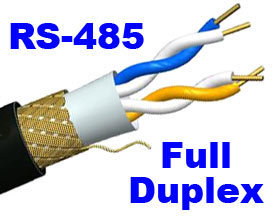
 Twisted pair wiring is recommended for RS-485 networks. Twisting minimizes loop area and susceptibility to magnetic fields. It also converts electrical interference into a common-mode signal that is rejected by the receiver’s differential input. Full-duplex operation requires a cable with two twisted pairs. These are usually enclosed in a shield that is connected to signal ground. Half-duplex requires only one twisted pair and a ground/shield lead. For noisy environments or extremely long runs, double-shielded cable can be used. The external shield is tied to earth.
While operation is possible without the signal ground connection between devices, it should be included to keep the common-mode voltage within the allowed range of -7 to +12V. Signal ground also improves system reliability and noise immunity. To eliminate circulating currents due to voltage differences between devices, a small resistor (100Ω) in series with the signal ground line going into each device is often recommended. It is not needed if the device has an isolated RS-485 interface (the 485 port signal ground is not connected to its internal signal ground).
Equipment
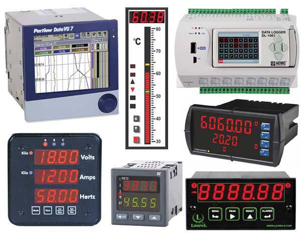
 The RS-485 interface is more common on instrumentation intended for fixed installation than on portable equipment. Some examples are (clockwise from the left): a panel mounted paperless recorder, digital bargraph meter, 8 channel data logger, dc ammeter, counter, temperature controller, ac power monitor.
The master device in a RS-485 network can be another instrument, but typically is a personal computer or programmable controller. Industrial computers often have a built-in RS-485 port. A RS-485 serial card can be added to a desktop computer. USB to RS-485 adapters are readily available to connect to a laptop’s serial port. RS-232 compatible products can be connected using an RS-232 to RS-485 converter. Longer distances or more devices can be handled by adding a RS-485 repeater to the network. Full-duplex devices may be configured for half-duplex operation by connecting their transmit and receive lines (A to A, B to B). Half-duplex devices make these connections internally, so they cannot be used for full-duplex.
RS-485 has proved to be a robust and reliable method for sending serial data. It is widely used in industrial applications. RS-485 is the physical layer for many well-known interface protocols, including Profibus and Modbus. This assures that RS-485 will continue to be a popular serial interface for many years.
