The purpose of a tap changer is to regulate the output voltage of a transformer by altering the number of turns in one winding and thus changing the turns ratio of the transformer. There are two types of tap changers: a de-energized (off-load) tap changer and an energized (on-load) tap changer.  The on-load type (LTC) is generally used on power distribution transformers to allow voltage adjustments while the transformer is supplying load current. The LTC can be installed on either the primary or secondary side of the transformer. It is often connected to the outside winding for easier wiring access and lower switching current. The LTC is normally motor and spring driven for automatic operation in response to load changes throughout the day.
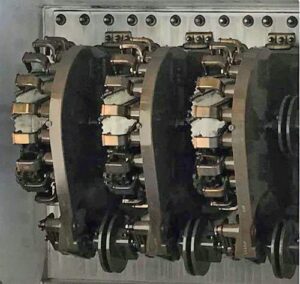
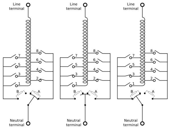
 The LTC is basically a rotary switch with make-before-break operation and extremely low contact resistance. There are numerous LTC types and designs. The typical LTC has 10-20 positions on either side of center, providing about a 10% voltage adjustment range. A multi-step switching sequence is required to handle the high currents. In this example, the tap switches 1-8 do not switch under load. The diverter switch at the bottom of the diagram switches the load. Elements A and B are resistors or inductors used to reduce the circulating current between taps during a tap change. Initially the neutral is connected to the winding through the tap 2 switch and the diverter switch (left diagram). Element A is shorted out. To initiate a move to tap 3, the tap 3 switch closes. The diverter switch starts to rotate, first breaking the direct connection to tap 2 and connecting only through element A. Next, the diverter switch also makes contact with tap 3 through element B (center). As the diverter continues to rotate, the contact with element A opens. All load current flows through element B to tap 3. Then the diverter shorts out element B and the tap 2 switch opens (right). The step sequence is complete, taking place in just a few line cycles.
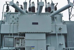
 To reduce contact arcing, the tap changer is immersed in insulating oil. In some models, the diverter contacts are housed in a pressurized gas bottle within this oil. Even so, arcing and contact wear will cause the LTC and oil to slowly deteriorate with use. Contact coking is also a frequent problem. To prevent contamination of the transformer oil and to facilitate maintenance operations, the LTC usually operates in a tank separate from the main transformer. The winding taps are routed into the tap changer compartment through a terminal panel.
Many power transformer failures are due to LTC problems. A healthy LTC generates very little heat when it is not switching, so the temperature of the LTC tank is typically lower than the main tank. When the transformer and LTC are operating normally, the long-term temperature differential between the two tanks is roughly constant. As the LTC switch contacts age or wear, their resistance increases.
One way to assess LTC condition is to monitor temperature. Heat generated from increased contact resistance raises the LTC fluid temperature. At some point, the heat becomes too great for the surrounding fluid to dissipate. Rapid contact degradation and LTC failure eventually occur. Before this point, an electronic temperature monitor (ETM) can provide warning of the increase in LTC temperature, allowing preventative measures to be taken.
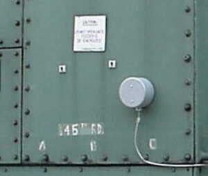
 On substation transformers that do not have a thermowell in the LTC tank, a magnetic surface sensor (see photo) is used to detect tank temperature. A matching sensor is placed on the main tank. To assess the condition of the LTC, the ETM compares the temperature readings from the two sensors over time. For transformers with a thermowell in the LTC tank, the preferred solution is to install a thermowell temperature probe. To assess LTC condition, the ETM compares the reading from this probe to the reading from a thermowell probe monitoring oil temperature in the main tank. For a true assessment, the ETM rejects transient temperature differences and alarms only when the long-term temperature differential exceeds a pre-set magnitude. Allowance is made for transformer loading, ambient temperature changes, operation of cooling fans or pumps, and other short-term effects.
A description of the settings and signal processing for load tap changer monitoring with the Weschler ETM is provided by LTC Temperature Monitoring.
