 In a hydroelectric power station, the wicket gate on a Francis or Kaplan turbine controls water flow into the unit. Varying the gate position changes the turbine spin rate and the amount of electricity generated. This photo shows a row of generators inside Hoover Dam. A turbine is mounted below each generator and water from Lake Mead is funneled into each turbine to turn its generator.
The wicket gate is a set of adjustable guide vanes surrounding the turbine that directs the water flow into the runner. The runner is connected to the generator shaft. These cut-away views show the wicket gate (yellow) at minimum flow setting (left) and at full flow (right). The runner is shown in red.

Originally uploaded by Stahlkocher at de.Wikipedia.
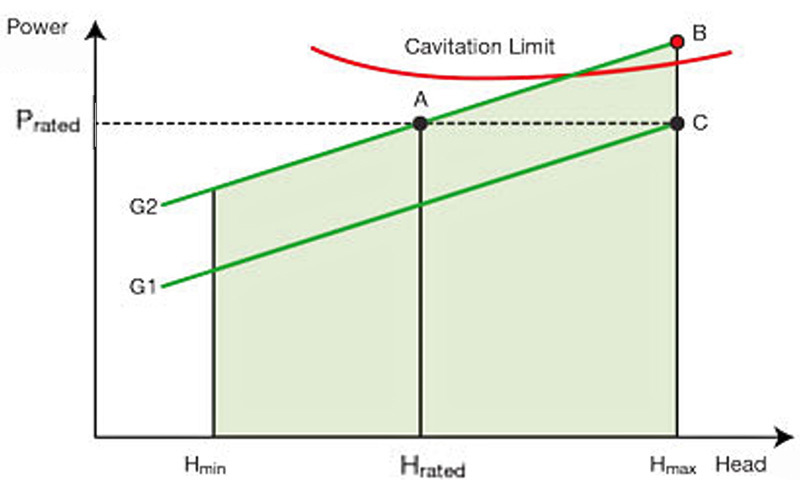 Generator output power is a function of head (the height of water in the reservoir). On the graph of power vs head, point A is the rated electrical power output at rated head, with gate position G2. At this gate opening, a higher head produces more power (point B) and risks causing cavitation. To maintain rated power output and safe operation (point C), the gate opening must be reduced to G1. The gate position may also be lowered to produce less than rated power when demand is low. Typically, the gate position is adjusted by a governor control and a gate limit is set by an operator.
 Early hydro controls included an analog gate position indicator (GPI). A precision potentiometer (aka Helipot) mounted to the wicket gate mechanism provided a voltage output proportional to position. This signal gave gate feedback to the governor control and was also displayed on an analog voltmeter. In some systems, it was routed through a current transducer that produced a milliamp signal to feed a remotely located 0-1, 0-20, or 4-20 mA GPI.
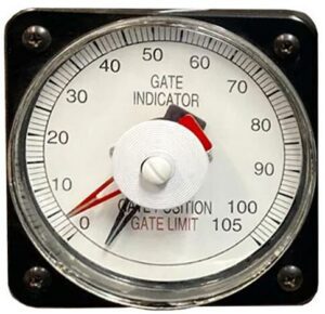
Simple gate position indicators only showed the gate position. The gate limit was displayed on a separate dial or meter. With this arrangement, it was difficult for the operator to determine the gate position relative to the gate limit. The preferred method used by Woodward Governor and others was to use a dual pointer meter to show both signals on one dial. The black pointer on this GPI shows the actual gate position; the red pointer shows the gate limit.
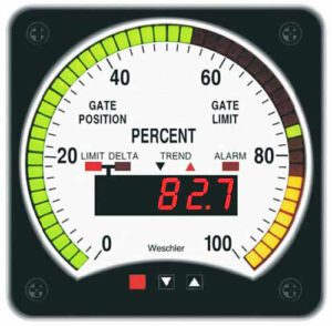 The digital replacement for this meter is the Weschler Gate Position Indicator. It is a specialized Tricolor BarGraph meter with two signal inputs. Gate Position and Gate Limit are simultaneously displayed in the LED bar. The operator presses the arrow button to view a precise position, limit, or difference readout on the 4-digit display. Two relay outputs are available to activate external alarms or initiate control actions. The trend arrow shows the last direction of gate movement. Three case sizes are offered: 4½” switchboard, 8¾” switchboard, 8″ round. One advantage of the bargraph display is the ability to vividly show if the gate position exceeds the gate limit. With the green gate position and yellow limit shown here, any overlap is indicated in red.
 Modern hydro governors use many schemes for generator control to optimize performance under varying conditions. A separate digital gate position indicator, along with a bargraph power meter, gives the operator a bright, easy-to-understand status check of turbine operation.
