There are two general methods for measuring ac currents:
- by direct connection with the current-carrying circuit
- by utilizing the magnetic field or flux generated by the current
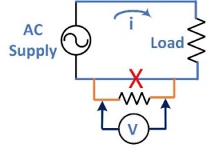 Direct connection to the current-carrying circuit involves breaking the loop. Typically, a low-value resistor is placed in series with the load and the voltage across that resistor is measured. The current is calculated using Ohm’s Law. This resistor is often referred to as a current shunt. For currents up to 20 amps, ac ammeters often have an internal shunt and read directly in amps (no
  calculation needed). Typical shunt values are 10mΩ for a 20 amp full-scale range and 100mΩ for a 2 amp range. At these current levels, a Kelvin (4-wire) configuration is used to improve accuracy. For higher currents, an external shunt is located close to the load. These shunts have large terminals for the high current connections and small terminals for the meter connections. Non-inductive construction can be used to increase bandwidth.
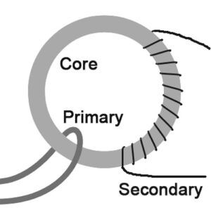 Current transformers (CTs) have primary and secondary windings on a magnetic core. The ac current in the primary winding produces a magnetic field in the core, which induces a current in the secondary winding. Typically, the primary winding has very few turns of heavy wire, while the secondary winding has many turns of fine wire. The ratio of turns between the primary and secondary determines the step-down ratio of primary to secondary current. Instrumentation current transformers typically use a toroidal core. In most installations, the primary conductor passes once through the center of the core (one primary turn). Since magnetic isolation separates the primary and secondary circuits, high voltage systems can be safely monitored with low voltage instrumentation.
 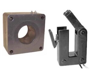 Standard secondary ranges are 1 amp and 5 amp. This level of the secondary current is easily wired to a meter or remote monitor. Installing a solid core CT requires breaking the circuit to route the conductor through the center of the CT. A split-core CT allows convenient installation since the circuit does not need to be broken. The two-piece core is placed around the wire and closed to complete the magnetic circuit. This is particularly useful when installing a CT around a busbar.
 A Hall sensor detects the presence and magnitude of a magnetic field. The sensor output voltage is directly proportional to the strength of this field. For a Hall effect current sensor, in place of a secondary winding, the Hall sensing element is placed in the gap of a toroidal magnetic core. The primary conductor is passed through the center of the core. Current in the primary conductor induces a field in the core, which is measured by the sensing element. Hall sensors pro
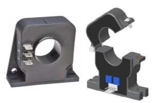 vide a non-contact, isolated method for measuring AC and DC currents. They come in a wide variety of sizes, from miniature sensors for measuring microamps to large devices for monitoring thousands of amps. Both solid core and clamp-on (split) styles are available. While these products may look similar to standard CTs, special signal conditioning is required. This circuitry could be included with the sensor or incorporated into a meter.
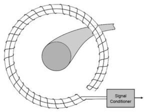 A Rogowski coil is a toroid of wire that measures an alternating current running through the conductor encircled by the toroid. The coil is wound on a non-magnetic form. The output of the coil is connected to an integrator circuit that generates an output voltage proportional to the conductor current. Rogowski sensors can measure a small ac current, even in the presence of a large dc component. The lack of an iron core provides a linear output, even when subjected to large overload currents.
 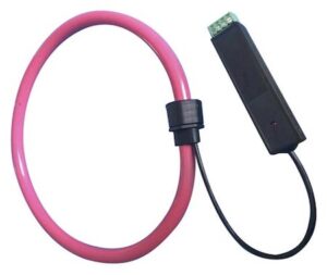 Their low inductance responds to fast-changing currents and harmonics. The Rogowski technique provides galvanic isolation between the high current and measuring circuits. The coil unplugs for easy placement around the current-carrying conductor. The flexible toroid encircles large cable bundles, bus bars, and irregularly shaped conductors in a way that regular clamps cannot. Common coil lengths range from 14″ to 60″, which is equivalent to a diameter of 5-19″. Larger sizes are available. Current ratings vary from 3 to 30,000 amps full scale. The current rating is independent of coil length. Like the Hall sensor, the Rogowski coil requires special signal conditioning. This is usually included with the toroid coil.
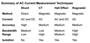 Selecting the AC current measuring technique depends on the application requirements and the available instrumentation. A future posting will discuss the instrumentation used for fixed and portable applications.
